Long Range Ultrasonic Testing - LRUT of Pipes

Long Range Ultrasonic Testing (LRUT) method is one of the bigest NDT method discovered and developed in last 20 years. In some NDT groups described as a Guided Ultrasonic Waves. Teletest® is a long-range ultrasonic non-destructive testing (NDT) technology developed for detecting metal loss in pipe-work. It is a pulse-echo system aimed at testing large volumes of material from a single test point. Its initial application was for detecting corrosion under insulation in petrochemical plant pipe-work, but it has found widespread use in other inspection situations where pipes or tubes are not accessible, for example where they are buried, encased in a sleeve or elevated above the ground.
Teletest® is primarily a screening tool. The aim of the inspection is to test long lengths of pipe rapidly with 100% coverage of the pipe wall and to identify areas of corrosion or erosion for further evaluation using other NDT techniques such as radiography or conventional ultrasonic inspection. The technique is equally sensitive to metal loss on both the outside and inside surfaces of the pipe.
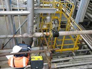
The system is entirely computer controlled, data acquisition and display/analysis being performed using a personal computer. The equipment in action on 6 inches pipeline is shown in Figure 1 and on 16 inches in Figure 2.
Principles of operation:

Teletest® employs low frequency guided waves, operating just above audible frequencies, propagated from a ring of transducers fixed around the pipe, Fig.2. These low frequencies (in ultrasonic terms) are necessary to enable the appropriate wave modes to be generated. At these frequencies a liquid couplant between the transducers and the surface is not necessary, satisfactory ultrasonic coupling being achieved with mechanical or pneumatic pressure applied to the back of the transducers to maintain contact with the pipe surface. The uniform spacing of the ultrasonic transducers around the pipe circumference allows guided waves to be generated that propagate symmetrically about the pipe axis. These may be visualised as a circular wave that sweeps along the pipe. The whole of the pipe wall thickness is excited by the wave motion, the pipe acting as a wave-guide - hence the term guided waves.
The propagation of these guided waves is governed principally by the frequency of the wave and the material thickness. Where the wave encounters a change in pipe wall thickness, whether an increase or a decrease, a proportion of the energy is reflected back to the transducers, thereby providing a mechanism for the detection of discontinuities. In the case of a pipe feature such as a girth weld, the increase in thickness is symmetrical around the pipe, so that the advancing circular wave front is reflected uniformly. Thus the reflected wave is also symmetrical, consisting predominantly of the same wave mode as the incident wave. In the case of an area of corrosion, the decrease in thickness will be localised, leading to scattering of the incident wave in addition to reflection and mode conversion will occur. The reflected wave will therefore consist of the incident wave mode plus the mode converted components. The mode-converted waves tend to cause the pipe to flex as they arise from a non-uniform source. The presence of these signals is a strong indicator of discontinuities such as corrosion. Teletest® is able to detect and to distinguish between symmetric and flexural waves and both types are displayed.
The reflections are displayed as rectified signals in amplitude Vs distance 'A-scan' display, similar to that used in conventional ultrasonic inspections, but with a time-base range measured in tens of metres rather than centimetres.
A major complication for guided wave systems as distinct from conventional ultrasonic inspections is the dispersive nature of guided waves; that is to say, the velocity of most guided waves varies with their frequency. This causes a variety of complications, one being that to calibrate the time base of the A-scan to read distance and not time, requires a computer program to read in a velocity for the selected test frequency from a calibration, or 'dispersion' curve. There is a library of dispersion curves built into the Teletest® software for a range of pipe diameter/wall-thickness combinations.
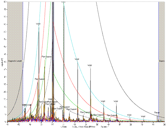
Girth welds in the pipe produce dominant signals in the A-scan and act as important markers, used to set a distance amplitude correction (DAC) curve on the display with which signals from anomalies can be compared - see below on Figure 3.

Applications:
- Road and river crossing
- Power plant tubing
- Risers
- Offshore topsides pipework
- Jetty lines
- Refinery pipework
- Chemical plant pipework
- Sphere legs
- Spiral welded pipe
- Stainless steel pipe
- Buried pipes
- Water underground nets
Flaws found
- External corrosion
- Corrosion under insulation
- Internal corrosion or erosion
- Environmental cracking
- Unknown branches or plugged holes
- Low cost screening with 100% coverage
- Focussing capability to evaluate corrosion distribution around pipe circumference
- Typical test range 60 meters from single location, ideal conditions can achieve 350 meters
- Testing of pipes up to 48 inches diameter
- Proven capability on pipe in service up to 125 degree C.
- Reliable detection of 9% cross section metal loss flaws
- Ideal where conventional testing is impossible or very costly e.g. clamped, insulated, elevated, underwater, sleeved or burried pipes
Benefits:

